ZONT можно подключить к котлам двумя способами – релейно и по цифровой шине. Оба варианта обеспечат дистанционное управление и автономную работу котла в выбранных режимах и по расписанию.
Релейное управление
При релейном управлении заданная температура поддерживается путем периодического включения и выключения котла и контролируется датчиком температуры, входящим в комплект поставки ZONT. В данном варианте ZONT подключается напрямую к котлу, адаптер для подключения не нужен.
Релейное управление котлом возможно, если у котла есть выход для подключения комнатного термостата (практически все современные электрические и газовые котлы).
Цифровое управление
При управлении по цифровой шине мощность котла регулируется плавно без частых полных выключений. Такой способ управления позволяет рассчитывать оптимальную температуру теплоносителя для поддержания заданного режима отопления и дополнительно дает более широкие возможности:
- плавное управление мощностью котла (модуляция горелки)
- дистанционное управление ГВС (если котел управляет ГВС)
- расшифровка кодов ошибок и аварий котла.
Внимание! Цифровое управление возможно, если в котле есть цифровая шина OpenTherm, E-Bus, Ariston или Navien и он совместим с ZONT!
Проверить совместимость и возможные способы управления конкретной маркой котла можно на странице совместимости котлов с ZONT .
В данном варианте для подключения ZONT необходим адаптер цифровой шины, плата цифровой шины или встроенный в прибор ZONT протокол (встроенный протокол есть не во всех приборах; он есть в термостате ZONT H-1 Navien, контроллере ZONT H2000+). Платы используются только для подключения регуляторов ZONT Climatic. Для остальных приборов используются адаптеры.
Адаптеры и платы цифровой шины OpenTherm, E-Bus/Ariston и Navien доступны в каталоге интернет-магазина tvp-electro.ru . Адаптеры типов «DIN» и «ECO» различаются только корпусом и способом крепления, по функционалу они идентичны и в равной степени подходят для работы с термостатами и контроллерами ZONT.
Внимание! Протоколы E-Bus/Ariston выходят на базе одного устройства (это может быть адаптер, плата или встроенный протокол). Одновременно в одном устройстве можно использовать только один из этих протоколов — либо E-Bus, либо Ariston.
Видео:LED status of the EMS bus GatewayСкачать

Шина ems bus протокол
Buderus Logamatic EMS and EMS+ bus Wiki for Bosch, Buderus, Nefit, Junkers, Worcester, Sieger devices.
Other names or versions of the EMS bus are EMS+, EMS Plus, EMS2, EMS2.0, Heatronic and Heatronic 3.
Junkers and Nefit also call it ‘2-Draht-Bus-System’ or ‘2-wire-bus’.
This repository is a collection of EMS protocol- and device documentation gathered from public sources like other Github repositories and of course my older documentation.
Will be filled in bit by bit.
See the Documentation folder for all information.
Links to existing EMS bus documentation
Links to existing EMS bus projects
Proddy’s EMS-ESP.
ESP8266 based code for communicating with and controlling EMS devices via MQTT.
Full support for Home Assistant Discovery protocol and support for Domoticz.
Proddy’s EMS-ESP32.
ESP32 based code for communicating with and controlling EMS devices via MQTT.
Full support for Home Assistant Discovery protocol and support for Domoticz.
BBQKees’ Arduino HTTP Get interface.
Simple interface for reading the boiler parameters and send the values to Domoticz via HTTP GET requests.
danimaciasperea’ Arduino WiFly interface.
Arduino and WiFly interface tailored to retrieving boiler parameters and controlling the RC35 thermostat.
Читайте также: Шин мин а возраст
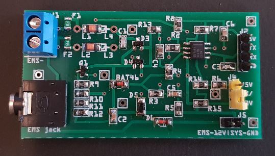
Links to EMS hardware designs


Видео:Как работает LIN шина автомобиля. K-Line L-Line шины данных. Лин шина автомобиля. Lin-bus networkСкачать

About
Buderus Logamatic EMS and EMS+/EMS Plus bus Wiki for Bosch, Buderus, Nefit, Junkers, Worcester devices
Видео:лекция 403 CAN шина- введениеСкачать

Шина ems bus протокол
Readout of Nefit/Buderus (Logamatic) EMS (=Energy Management System) interface Protocol by Arduino and transfer of data via HTTP GET requests to Domoticz home automation software (or to other systems).
There are also other names for ‘EMS’ or additions to EMS called EMS+, EMS2, Heatronic and Heatronic 3 but for most of those you need to do additional reverse engineering.
Although the code in this repository works fine for the most part, I suggest you have a look at the ESP code from Proddy. It has support for lots of boilers and thermostats out of the box, it’s well maintained and features are added all the time.
I have written a plugin for Domoticz and EMS-ESP supports Home Assistant natively.
I’m also transferring most documentation to my dedicated wiki repository EMS-Wiki.
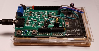
You can purchase a complete and tested interface board here.
Readout the Nefit/Buderus EMS interface of a Nefit Trendline gas boiler (gas condensing central heating boiler).
Transfer of data via ethernet to Domoticz home automation software.
The main sketch reads the EMS interface data and depending on the format decodes the data and puts it in variables. You can then send the values via HTTP GET requests to Domoticz or do whatever you want with it. Usage is not limited to Domoticz, you can extract the decoding part for other purposes.
There are also a few other sketches here to help you read and write to the EMS bus.
Furthermore there are some schematics here to help you build the converter circuit.
(Or buy a complete converter board here.)
Reading the EMS bus: Should support all boilers using the EMS databus. This includes most Bosch boiler brands like Nefit, Buderus, Worcester, and some Junkers. But also f.i. Sieger.
Datagrams containing status updates are periodically sent out by the boiler with source ID 0x08. You only need to listen in. No data requests are needed for most boilers (But some only send the status automatically at boot).
However, several types of data are only send when the specific device on the bus is polled. For this you need to write to the bus.
Writing to the EMS bus: To change the temperature and other settings you need to write to the thermostat on the bus. This needs to be a EMS thermostat. Depending on the thermostat on your wall you need to send specific commands. Most of these are already reverse-engineered. Some are not. Below the list of thermostats which should work fine.
Nefit and Bosch boiler types with EMS bus
This list below is incomplete and no longer maintained. Check the full compatibility list here.
- Nefit 9000i
- Nefit TopLine
- Nefit TrendLine
- Nefit ProLine (only the non-NxT!)
- Nefit SmartLine
- Nefit BaseLine
- Bosch Compact
- Nefit EcomLine Elite (Just the Elite, older sub types often have the old iRT bus!)
- Sieger BK 15
Nefit and Bosch boiler types with -NO- EMS bus
The following boilers have no EMS bus and are thus not supported:
- Older Nefit EcomLine models like the VR24V, HR(C), Economy, HRC23VT (iRT protocol).
- Nefit ProLine NxT (OpenTherm protocol)
- Bosch HRC / HRC Top / HRS Top
- Bosch HRCII / HRSII
- Nefit Turbo
- Bosch Condens 3000W / 6000W
For the most specific info have a look at the EMS thermostat documentation page.
Short info:
EMS bus thermostats: RC20 (source ID 0x17), likely also RC30 and RC35 (both ID 0x10).
Depending on under which brand name these thermostats are sold they might have a different type name.
Some of the thermostats below are multi-protocol!
This means that although the thermostat will support the EMS protocol, they also support the older iRT protocol.
So if you have an old non-ems boiler like the Nefit Ecomline, you cannot use the code and the schematic in this repository.
| EMS code | Buderus type | Nefit type | Image |
|---|---|---|---|
| 0x17 | RC10? | Moduline 100 | |
| 0x17 | RC20 | Moduline 200 | 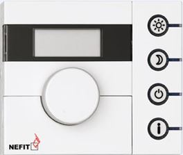 |
| 0x10/0x17 | RC30 | Moduline 300 | 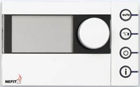 |
| 0x10 | RC35 | Moduline 400 |  |
The RC30 is equal to the Nefit Moduline 300 and the RC35 is equal to the Moduline 400.
The RC20 is likely equal to the Nefit Moduleline 200.
Although the hardware is identical (if you open up a ModuLine 400 it says ‘RC35’ on the PCB), the firmware may be a bit different. It appears there are slight differences in frametypes. However, as more people are using theses sketches this will be resolved over time.
Furthermore in principle all EMS bus thermostats can be supported. So this also includes the Nefit Easy and the new line of ModuLine series 1000, 2000, 3000 etc. For a new thermostat you need to log the data on the bus when you set the temperature on the thermostat and go through the log to find the correct messages.
If you have a newer Nefit/Bosch/Buderus EMS thermostat and you would like to help I can give a hand. You can contact me via the Domoticz forum.
Non-compatible thermostats
| Buderus type | Nefit type | Image |
|---|---|---|
| iRT30 | ModuLine 30 | 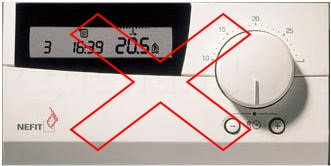 |
If you have an older thermostat looking like the one above, your boiler is NOT compatible with the EMS bus.
If your thermostat does not work, and you really want to change the temperature you might want to buy a supported model.
This Github page of Danidata has a very similar approach that works with the RC35.
You do NOT need to have an EMS compatible thermostat or a thermostat on the bus at all if you only want to read out the common status messages from the boiler!
Status updates regarding many parameters of the boiler are sent to the bus every 10 seconds.
I f.i. have an on/off thermostat zone control. So I do not have a Nefit thermostat at all. By connecting the EMS bus circuit to the service jack, I can still capture those status updates.
It is only if you want to read or write thermostat settings you need an EMS bus thermostat.
- EMS interface circuit (See Documentation or PBC-files folder).
- Arduino Mega 2560 Rev3 + Arduino Ethernet Shield with Wiznet w5100
- Raspberry Pi, PC or other device running Domoticz
The EMS bus interface can be converted to TTL level by means of a simple circuit. The TTL-converted signal can then be connected to one of the the Arduino UARTs. See the Documentation folder.
The sketches here use the Arduino Mega 2560 and the Wiznet 5100 ethernet shield. You can also use another Arduino like the Uno but that one only has one hardware serial port.
Serial1 is used for the EMS module. Serial(0) is used to debug the output to PC. EMS serial works with 9700 Baudrate and 8N1. You need a modified Serial library for the Arduino. It’s included in the project.
The modified Serial library and thus the entire sketch will only work on Arduino (compatible) boards that have an Atmel AVR (ATmega) microcontroller on board like the Uno and Mega. ATSAMxx (ARM) type Arduino’s are not supported. Neither are the ESP8266, ESP32 etc.
For the ESP8266 ‘Proddy’ has written fully working code: https://github.com/proddy/EMS-ESP-Boiler
- Serial on pins 0 (RX) and 1 (TX),
- Serial1 on pins 19 (RX) and 18 (TX),
- Serial2 on pins 17 (RX) and 16 (TX),
- Serial3 on pins 15 (RX) and 14 (TX). You can choose any of the Serial ports on the Mega, the current sketch uses Serial1 but you can change that.
Arduino non-Mega: You cannot use Serial1, so you need to use Serial(0), which does not allow for combined debugging via serial.
Where did you find all the information about the bus?
It should be noted that the reverse-engineering of the EMS bus protocol was a major effort that involved many people. Most of it all started a few years ago on the mikrocontroller.net forum. Below two topics that hold all the original information:
http://www.mikrocontroller.net/topic/309075
http://www.mikrocontroller.net/topic/141831
At a later stage all information got nicely bundled at: https://emswiki.thefischer.net/doku.php?id=start
In the end I combined code acquired from ‘Jvdmeer’ from the Nodo forum with methods to interface with Domoticz and published it here with lots of additional documentation for all to use.
How about MQTT instead of HTTP GET requests?
That is on my list (maybe). For now it works exactly like my other Github project ‘Vbus-Arduino-Domoticz’.
How about serial output instead of HTTP GET requests?
If you use a Mega, this is very easy to accomplish. Just check f.i. ‘this website’. It will not work easily with an Uno, because you would need to use the software serial for reading the bus, this would also need modification to its library. But a Mega 2560 Rev3 is only a few Euro/Dollar on Ebay or Aliexpress anyway.
Sketch is based on the EMS sketches from ‘Jvdmeer’ from the Nodo forum.
Which license applies here?
The MIT License. This means that you can do whatever you want with my code! No need to ask me. It is always nice however to publish your version to Github to help others.
‘Worcester, Bosch Group’, ‘Buderus’ and ‘Nefit’ are brands of Bosch Thermotechnology.
All other trademarks are the property of their respective owners.
Видео:Экспресс диагностика CAN шины на автомобиле. №21Скачать

About
Readout of EMS protocol datagrams and transfer of data to Domoticz via Arduino
📸 Видео
Протокол MODBUSСкачать

Адаптер KKL VAG COM 409.1 - как сделать диагностику автомобиля своими рукамиСкачать

Автоматика ZONT H-1V обзор, монтаж и возможности. Цены в Описании.Скачать

Подробно про CAN шинуСкачать

Horrifying incident: On camera speeding ambulance crashes into a toll plaza in Karnataka | Zee NewsСкачать

Плюсы и минусы сервисной шины данных I Enterprise service bus (ESB) I kt.teamСкачать

Подключаем GSM Термостат ZONT SMART. что нужно знать, основные особенности подключения.Скачать

Новый премиум | SERES AITO обзорСкачать

Canbus - зачем он нужен? И как его настроить.Скачать

Подключение теплосчетчика к электронному регулятору ECL Comfort 310 по линии связи m-busСкачать

Secrets of Junsun car radios for Android and once again about connecting a rear view cameraСкачать

Системы управления отоплением Buderus EMS PlusСкачать

Интеграционные шиныСкачать

Как подключить GSM термостат Zont H-1V к котлу Протерм Скат 12 кВтСкачать

GSM термостат ZONT (типовые ошибки при настройке)Скачать

